
Reflow soldering is a relatively recent addition to the electronics industry, ushered in to allow the usage of SMT (surface mount technology) parts. Today, reflow soldering is what makes every cell phone and almost every consumer electronic device work. The automation possible as well as the overall quality of solder joints make it an easy choice for most electronics projects. In the picture above, solder paste has been applied to the circuit board and is awaiting part placement and reflow soldering.
As mentioned in our last post detailing moisture sensitivity levels and the need to bake parts, this post dives into enabling reflow soldering using a Tiny Reflow Controller V2 by Rocket Scream. We will cover reflow profiles and briefly discuss their different aspects. As each reflow oven is different (our first one is an old toaster oven, the building of which is detailed here), the reflow profile will likely need to be adjusted to get good results with your own oven. We share our first 3 trials at the end of this post, along with some of the challenges we encountered.
Some Background Information About Reflow Soldering Profiles

The image shown above is a reflow profile for a popular leaded solder paste. If you look at the top of the figure, you will notice that there are four distinct zones to the reflow profile: “Preheat”, “Soak”, “Reflow”, and “Cool Down”. In addition, these all occur in under 5 minutes. This is why it is so important to have a controller AND to have a very well insulated oven. If the oven is not well insulated, it will never heat up quickly enough to complete the profile in time. This will result in poor solder joints, where the flux has all burned off before the board even gets up to reflow temperatures.
As mentioned previously, there are four different reflow zones. The first, “Preheat”, is a steady ramp up to ~155 C. The goal of this ramp is to get the board heated up safely and to allow for the solder paste to outgas safely. As the figure above shows, the ramp rate should be less than 2.5 C / second.
The second zone is “Soak”. The purpose of this stage is to continue the outgassing of volatile compounds from the solderpaste, to begin activation of the flux and to continue allowing all components to rise in temperature. The activation of the flux is quite critical when it comes to the time and temperature of the soak. If the soak period is too long, the flux will be consumed and parts may not solder well. If the temperature is too low, the flux may not activate fully, allowing oxidization on the PCB pads and component leads to remain.
In addition, “Soak” is where leaded and lead-free profiles begin to diverge. If you view the figure below, you can see how while leaded solderpaste almost plateaus here, lead-free continues to heat at a slightly slower rate as the “Pre-heat” zone.
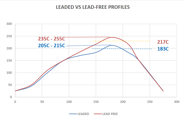
The third and most important stage is “Reflow”. Looking again at the EP256 profile, the ramp up to reflow temperatures is very quick, as well as the ramp down. The time above the melting point of solder is typically 45 seconds for leaded and lead-free pastes, but for lead-free alloys without silver, this is typically 60 seconds.
The fourth and final stage is “Cool-down”. As the name implies, this stage is to quickly lower the temperature of the assembly from reflow temperatures, back down to a temperature below about 100 C. The rate of cooling should be near 4 C / second.
Profiles with the Tiny Reflow Controller V2
Now, we can dive into some of our first profiles using the Tiny Reflow Controller V2. We started out using the default profile and PID settings the controller came with. We decided to not put anything into the oven this first time, just in case something went wrong, which turned out to be a good idea!
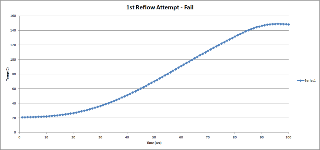
The plot above shows the result of the first run. The horizontal axis is time in seconds, and the vertical is temperature in C. The oven was not able to reach the necessary temperature of 150 C in order for the controller to go onto the next stage (“Soak”). This would have been detrimental, had an actual board been in there, because the temperatures would have started activating the flux. The amount of time needed to stop the oven, fix the issues and then go back in for another reflow would have meant the amount of flux remaining would have been drastically reduced. In another blog post, we go into detail on how to fix this issue. To quickly summarize here, we adjusted the PID coefficients which allowed for the required temperature to be reached, and the “Soak” stage to begin.
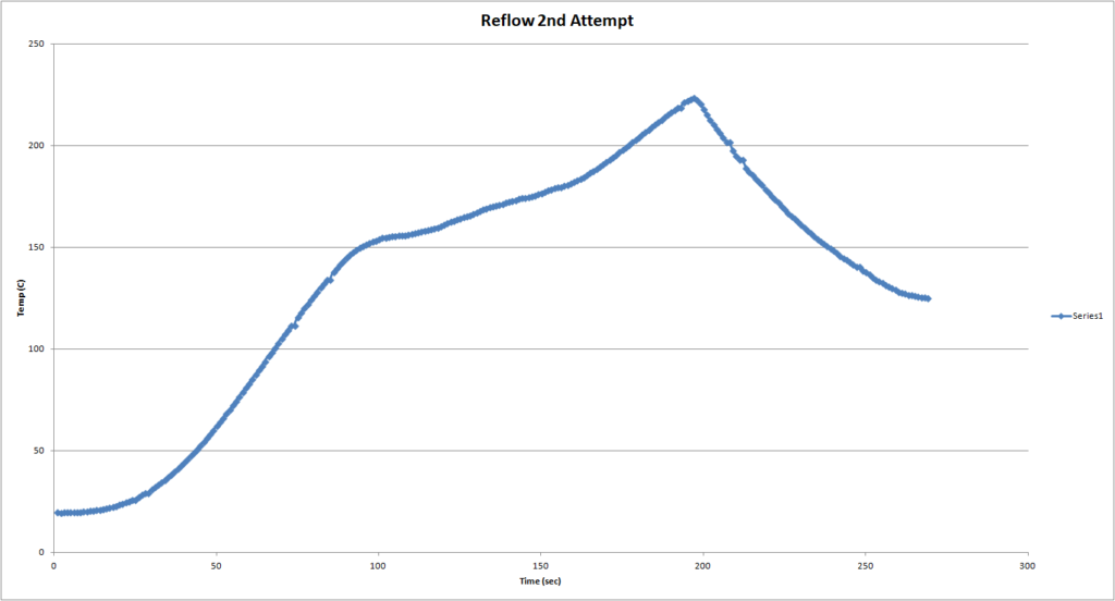
The plot above shows the reflow profile for our second attempt. The “Pre-heat” stage ramped at approximately 2 C / second, which is where we were targeting. The final temperature was 223 C, which is a bit high. The suggested maximum temperature is 215 C with a +/- 5 C tolerance. Even with the tolerance, we were 3 C out-of-range. This can cause many issues, but the most noticeable are dull solder joints and damage to flux. Fortunately, we did not see these.
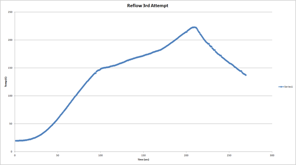
Our third and final attempt that we will detail in this post is shown above. Our maximum temperature still reached 223 C, but that does show the oven and controller do have a high level of repeatability. We will work to further optimize the profile, but for simple prototyping, it is more than sufficient.
Concluding Thoughts
Overall, we are very impressed with the performance of the Tiny Reflow Controller V2 combined with a simple toaster oven. With less than $100 worth of materials, we are able to do our own reflow soldering in-house. This is a significant time and money saver. We did notice some issues, such as the need to adjust PID settings on the controller which we detailed above. In addition, on larger boards, we have noticed that some areas get hotter than others. This is most noticeable when crossing the melting temperature of the solder paste – some parts have reflowed while others have not. With additional time all parts do solder, but with a fairly consistent distribution of copper on the board, we expected this to be better. We attribute this to the toaster oven using IR (infrared radiation). This means that IR is not evenly distributed and parts directly under the heating element warm faster than those that are not. In addition, darker colored parts absorb heat more quickly than parts that are lighter in color. Commercial reflow ovens typically use convection heating, or even vapor phase heating. These however, are far out of our budget for equipment at this time. Overall, we are impressed with the setup and will use it to bring you designs for your own workbench!
Leave a Reply